
I think in every machinist’s life there is a moment when hand-cranking that z-axis table or head becomes almost unbearable pain in the rear. In my case it was when I had to make a part with a lot of holes of different sizes. It went something like this: Indicated the part. Cranked the head up. Installed the drill chuck and chucked the center drill. Cranked the head down. Started the hole. Cranked the head up. Replaced the center drill with the correct size drill bit. Cranked the head down. Drilled the hole. Removed the part from the vise and re-oriented it for the next operation. Repeated all the steps from the beginning. And it went on and on and on.
Recently while shopping for something else on Amazon, I came across an interesting little gizmo called ZK-SMC01 Stepper Motor Controller. Turns out it’s very popular little controller, it comes in two different versions (with and without stepper motor driver), and it’s available from many vendors and under different names. Well, it did look like a good start to me, it’s got Up and Down buttons and a potentiometer to adjust the speed, so…can I use it for my custom power lift design?
I purchased this stepper motor kit from the Stepper Online, I figured it is powerful enough to lift the heavy machine head. I also got a small power supply to power up the controller and the cooling fan and I wired everything together on my workbench to see how it works. And it worked!
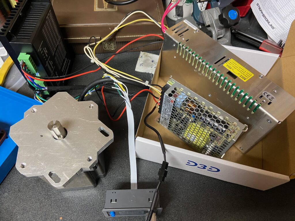
The mounting plate looks weird because the footprint of the Nema 34 is very similar to the dimensions of my mill’s column, so I had to improvise. It looks ugly but who cares. I’m not Miss Arizona myself, if you must know. Actually…why not? Who said a man cannot be Miss Arizona? Fine, how about Miss California? But I digress.
To connect the motor to the shaft I was initially planning to use another bevel gear, same as the one currently in the mill. But I couldn’t find out its specs, and it was probably not a good idea anyway. So I got a lovejoy coupler from McMaster, tapped an M12 thread in one of the halves and threaded it onto the shaft instead of the locking nut that was originally there. I put another half on the motor shaft and installed everything on the column. Connected all the wires and presto! It worked great!
My plan was to 3d print the enclosure for the electronics but it was only partially successful. I printed the lid, but in the middle of printing the box my printer failed. It skipped layers, threw spaghettis everywhere and when I tried to restart the print, it crashed in the middle of the bed leveling process. Yeah, I see the Bambu Lab X1C in my future, but not so near future…
In the meantime I decided to bite the bullet (.452 200gr LSWC, to be specific) and ordered the print from one of the online 3d-printing services. The price was very fair, just a tad above an average price of a spool of PLA filament, so no big deal. But now we wait…
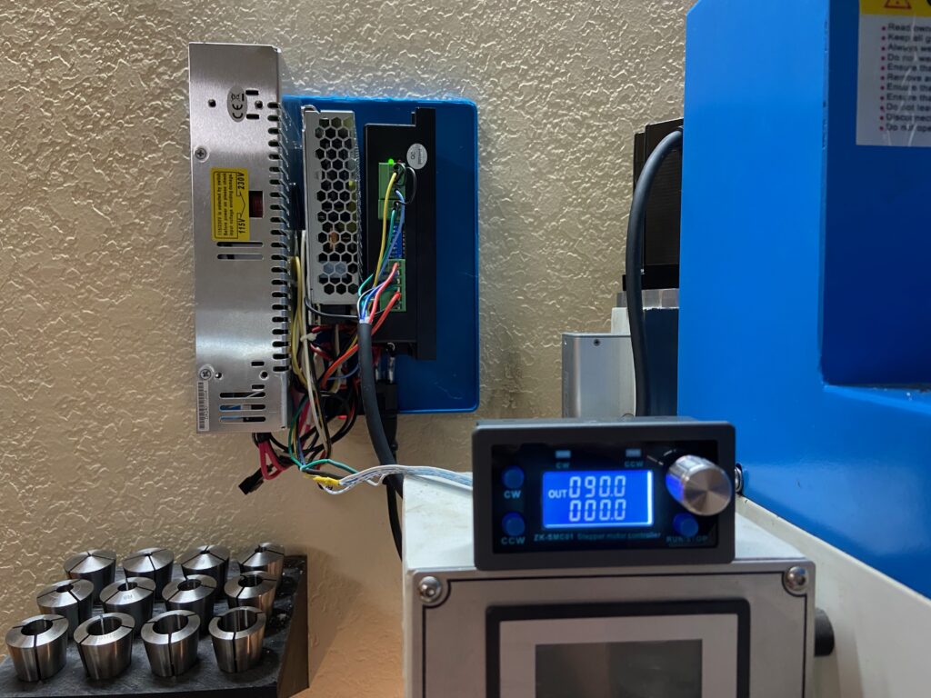
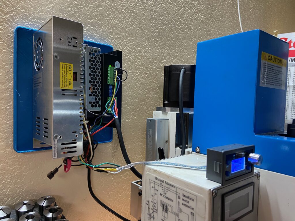
In the meantime I temporarily mounted it on the wall and connected all wires. Yes, I know, there’s nothing more permanent than temporary, but I will definitely address this as soon as the new enclosure arrives from the 3d printing service. If I leave it open like this, sooner or later flying chips will make their way into the electronics and start fireworks.
But for now it’s functional, and I can’t stop playing with it. Up and down, up and down…