
The Precision Matthews PM-1130V is a very capable machine. It has everything I need, but there’s one major drawback for me – the external change gears. Every time I needed to change feed rate or cut a new thread, I had to perform a set of pole dances around the lathe, taking off the side cover, loosing nuts, pulling the gears off, etc, etc. – very time consuming and tricky to do in a tight space. So I started looking for options. And the first one I found was an excellent set of YouTube videos by James Clough aka clough42. He designed the ELS for his Grizzly lathe, all the components are readily available and relatively inexpensive, and he provided a very detailed walkthrough that covered all important aspects of the design and build.
So I purchased all the components he listed on his Github Wiki page and proceeded with the build.
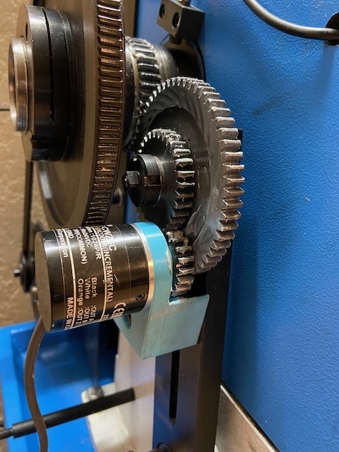
The first step was to find a way to mount the encoder. I found this Thingiverse page, printed the bracket, used the gears that came with the lathe, installed everything and verified that at least mechanically it works as it should.
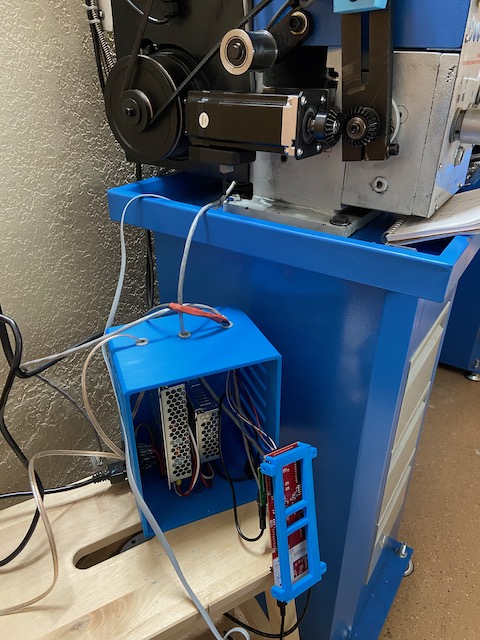
Next ones were the enclosures for the electronics and the control panel. I kept my 3d printer busy for a week or so but the result was a nice box that I designed in Fusion360, with holes for the switch, power supply mounts (I used separate 48V power supply for the motor and 5V supply for the electronics and fan) and mount for the controller.
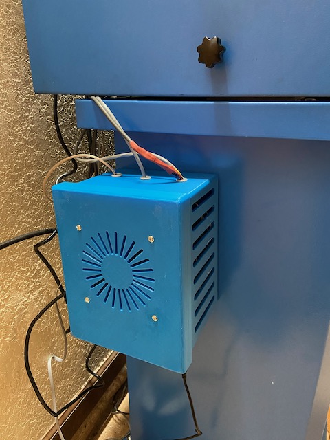
It’s held to the side of the stand by a few magnets I glued to the back of the box.
The most challenging part was mounting the motor. I had an impression I could have 1:1 ratio between the motor and the lead screw shaft and also I didn’t want to mount it coaxial to the shaft, because I still wanted to be able to put the side cover on and not having to cut an opening for the motor. So I came up with the bevel gears and 90 degree mount, like this:
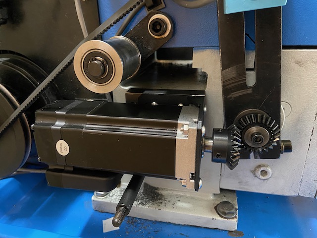
After I turned everything on, I realized my mistake – the motor simply does not have enough power to rotate the shaft at this speed. So 1:1 ratio was not an option.
I finally figured out a way to mount the motor so that I can use timing belt and pulleys. There’s a tiny bit of space between the lathe casting and the lathe motor, barely enough to squeeze this motor in between them (and I had to file the casting just a little bit). I installed the motor and ordered some pulleys and belt from Amazon. Turned out the belt I need is exactly 513mm in circumference and 171 teeth.
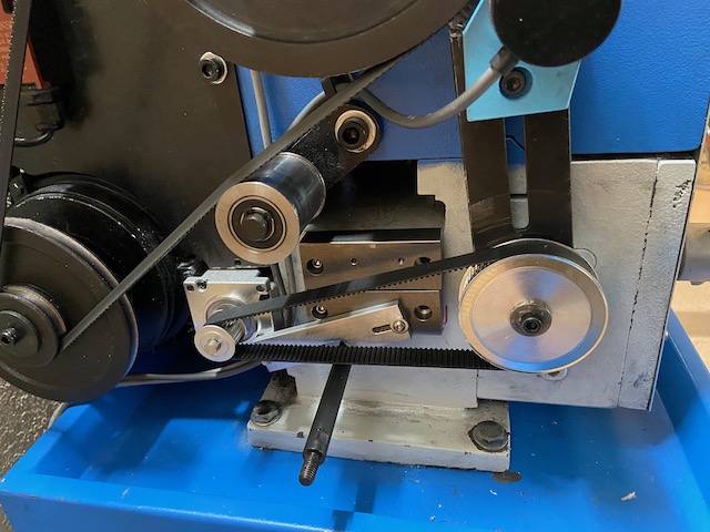
Now everything works perfectly! I tried to cut a few test imperial and metric threads and everything works perfectly. Many thanks to James for the great design and instructions!
This is really nicely done! Can you share links to the pulleys and belt you used? How do you like the lathe? How often do you switch between the 2 spindle speeds and how hard is that to do?
The pulleys are from the eBay: https://www.ebay.com/itm/163542838348
The belt is from Amazon: https://www.amazon.com/gp/product/B00J9U9N1E/ref=ppx_yo_dt_b_search_asin_title?ie=UTF8&psc=1
It does seem though that the 1:3 ratio is barely enough, so I’m thinking about getting a 120T pulley and trying a 1:5 ratio.
The lathe is great, it does everything I need, but the speed ranges are a bit awkward, I’m currently on the low range and at 500 RPM I get a somewhat questionable surface finish. Seems like I need to spin it faster, but then I will lose the lower range and power tapping functionality. So yeah, it is a compromise. It’s not difficult to change the speed range, just time consuming.
Other than that, I’m very happy with the lathe. A few small things that I changed were the new screw with the handle for the carriage locking and the new nut for the toolpost.
Thank you for your response! That is good to know.
Agree on well done. Hope you are still listening here.
I have an 1130 and am about to get into the mechanics of this change.
I am wondering how you fit the stepper motor in that space. On my 1130 there is a brace for the spindle motor in that space. Haven’t done detailed measurements yet but seems very tight.
thanks
Kevin
In my case I just had to file down the casting a little bit, and the stepper motor went right in, as if it was always meant to be there. You can also loosen the spindle motor mount screws a little bit and wiggle it around.
This looks like a great mod,i was wondering if you have done any rifle barreling and chambering on this with the 1-1/2 inch spindle bore.
Not rifle but pistol barrel chambering, yes. I do have a rifle project in the pipeline but I need to make a spider for the spindle first, it may be a bit tricky because there’s not a lot of material on the left side of the spindle, I will probably need to make a custom spindle nut.